
News Article
On-site generated fluorine: effective, safe, and reliable source of fluorine for electronics for over 15 years
On-site fluorine generation has proven a safe alternative to greenhouse gases often used in electronics manufacturing. Linde delves into its makeup, history, and how fluorine is effectively used to clean CVD chambers and in many other applications. By Dr. Paul Stockman, Head of Market Development, Linde Electronics
On-site generated fluorine (F2) is a safe and reliable alternative to greenhouse gases for chemical vapor deposition (CVD) chamber cleaning and is currently used in the commercial production of semiconductors and LCD screens in multiple sites in Asia and Europe. In the first of a two-part series, we describe the on-demand production of high-purity fluorine as demonstrated by Linde's installed base of more than 30 generators serving global industries over 20 years and electronics manufacturers for more than 15 years. Production capacities ranging from 1 to 100+ tons / year have displaced high-pressure fluorine cylinder and bulk nitrogen trifluoride (NF3) supplies. Certification by leading safety and engineering authorities document the design details required to effectively deliver fluorine reliably and safely without incident. In Part 2, we will describe the fundamental physical properties of fluorine, which are the basis for significant process and cost of ownership improvements and which eliminate the need for greenhouse gases in chamber cleaning.
History of fluorine
Fluorine was first produced and isolated by the French chemist Henri Moissan in 1886. However, the challenges in production processes and the element's vigorous reaction chemistry limited its use to bench-scale apparatuses for small experimental quantities. Industrial-scale production technology was first developed for the Manhattan Project in 1943 when gas-phase uranium hexafluoride (UF6) was identified as the preferred method for separating the fissible 235U isotope from the remaining 99 percent of isotopes. After the war, fluorine production technology was further developed and proliferated with the spread of independent nuclear materials capability and from this base further non-nuclear applications were developed.
Today, tens of thousands of tons of industrial fluorine are produced commercially all over world as chemical feedstock for organic fluorides and various inorganic fluorides such as SF6, NF3, and boron trifluoride (BF3). Additionally, industrial fluorine is used for chemical modification of surfaces and to make certain plastics impermeable to water, oxygen, and hydrocarbons.
While industrial fluorine can be transported in large volumes either as a cryogenic liquid or as a compressed gas, safety and logistic concerns dictate that most fluorine is produced and consumed on-site and on-demand at low or atmospheric pressure. This limits both absolute inventory of fluorine, because it is only made as is needed, and also prevents high-energy, high-pressure events because the reactivity of fluorine is directly related to its pressure.
How fluorine is produced

Fluorine is produced by electrolysis of anhydrous hydrogen fluoride (HF) to yield hydrogen (H2) gas at the cathode and F2 gas at the anode; the amount of gas evolved is directly proportional to the current applied. The process is similar to the electrolysis of water to produce H2 and oxygen (O2); however, it requires the salt potassium bifluoride (KHF2) as a charge carrier and transport medium. The HF consumed by electrolysis is replaced by adding HF gas or HF liquid directly to the salt-acid mixture, with an effective composition of KHF2 Ÿ (HF)x≈1, which melts at 72O Celsius. The electrodes are physically separated to prevent the rising H2 and F2 gas bubbles from recombining, and the gases are evolved over the melt and collected through separate vents. Material selection of electrode and cell body components is essential to ensure a long operating lifetime of the fluorine cell with minimum maintenance requirements, and periodic chemical analysis of the salt-acid mixture verifies the integrity of components.
HF dissolved in the molten KHF2 salt is electrolyzed to produce H2 at the cathodes and F2 at the anodes. The HF2 feed can be introduced either as a gas or a liquid.
The evolved streams of both H2 and F2 contain 1-5 percent of HGas as a vapor-phase impurity. The H2 stream is diluted to concentrations below the LEL (lower explosion limit) of 4 percent and scrubbed before being vented to atmosphere. For high-purity applications, the fluorine stream is purified to remove the HGas as well as other low-level impurities. Compression to a working pressure of 1.0 to 1.5 barg and buffering in a temporary tank provides an adequate process supply at constant pressure without creating excess inventory.
Anhydrous HF, either in gas cylinders or larger bulk containers, is used to feed the fluorine cell. The H2 byproduct is extracted for disposal, while the generated fluorine is further purified before being compressed to 1 to 1.5 barg and temporarily buffered before use in the customer process. All key process modules are enclosed in extracted cabinets as part of the safety design.
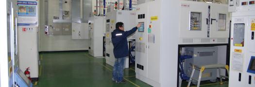
On-site fluorine generators
Concerns for safety and reliability have informed the design of on-site fluorine generators for use in the high-tech thin-film industries of semiconductor, display, and photovoltaic manufacturing. As with any chemical introduced into these market sectors, safety risks need to be identified and mitigated. Fluorine is the most electronegative element from the periodic table and this extreme reactivity is the cause for risks to both health and equipment.
Fluorine falls in the middle of the spectrum of the many toxic gas-phase chemicals commonly used in thin-film device manufacturing, a few examples of which are shown in Table I [Reference: American Conference of Governmental Industrial Hygienists]. Mitigation strategies focus on three areas: material selection and passivation, containment, and design for minimal inventory.

Mitigation strategy: Material selection and passivation
Although fluorine is highly reactive, many common metal constructions are compatible with fluorine at process temperatures. These include brass, copper, nickel, and many steel and nickel alloys, all of which form chemically inert, passivated metal fluoride layers when properly prepared.
Components for the generation, containment, and transport of fluorine should first be cleaned of all particles and residues "“ the same as for oxygen service "“ and certified leak-free. They are then exposed to a sub-atmospheric partial pressure of fluorine, often diluted in an inert gas.
Any organic residues are converted to gas-phase fluorides and exhausted to a scrubber, while the native oxide layers of the metal are replaced to form metal fluorides. By gradually raising the partial pressure to the maximum working pressure, the metal fluoride passivation layer is deepened, and the metal surfaces are rendered inert to further reaction with fluorine.
In addition, properly-sized piping and elimination of sharp bends are required to reduce gas velocities below the industry-recognized safe levels [Reference: Compressed Gas Association CGA publication 9-15; European Industrial Gas Association EIGA document 140/10].

Mitigation strategy: Containment
Containment forms the second safety risk mitigation strategy. All super-atmospheric sources of fluorine are contained by either ventilated enclosures or sealed and sectioned annular piping.
Ventilated enclosures house all generation and compression equipment, purification and buffer vessels, and valve manifold boxes. Extraction rates are determined to maintain safe external conditions in the event of a rapid release of the limited inventory. Extracted air is treated by either a local or facility acid scrubber.
Toxic gas detectors specific to fluorine are used to monitor all extracted areas. Transport of fluorine within the facility is through double-layered piping. The fluorine flows in the center tube while the annular space is sectioned and pressurized with nitrogen.
A leak from the center tube can be detected as a pressure loss in the annular space, and fluorine is doubly contained by both the outer pipe and the nitrogen barrier. A leak detected by a toxic gas monitor or by depressurization of the annular containment triggers suspension of fluorine generation and automated closure of fail-closed valves.
Mitigation strategy: Design
On-site fluorine generation has been sized to meet the requirements of a number of thin-film chamber cleaning processes. Originally conceived as a replacement for high-pressure cylinders of F2 and ClF3 (chlorine trifluoride) used for cleaning low-pressure chemical vapor deposition (LP-CVD) semiconductor equipment, the smallest sized units have an annual production capacity of 1 ton / year. The equipment is designed in standard modules with form factors similar to gas cylinder cabinets.
Along with the availability of gas blenders with very low pressure-drop components, these units make for a direct replacement of 20 percent F2 / 80 percent nitrogen (N2) cylinder supplies. Almost all safety incidents in the semiconductor industry with fluorine are associated with high-pressure cylinder supplies, and in particular, the regulators used. Because a single generator operating at low pressure can replace more than 500 cylinders per year, the safety of the process has been greatly improved.
Maintaining a minimal inventory is integral to the design and safe usage of fluorine. Because the fluorine is generated on-site, there is no need to compress it to high pressures in order to transport it in containers. Instead, a pressure of 1.5 barg is sufficient to supply all gas conditioning and mass flow equipment of the cleaning process. And because fluorine is generated on-demand and proportionally to the current applied to the electrodes, the only vessels used are sized to buffer the generator against the periodic requirement for cleaning gas.
Modeling of randomized demand from multiple tools, sometimes numbering more than 100 for a single on-site plant, ensures that the buffer vessels are sized adequately for all realizable demand without being oversized. For example, a plant with a name-plate capacity of greater than 100 tons / year has an instantaneous inventory of less than 50 kg, which is little more than four hours of supply for a large LCD fab; fluorine supplies for semiconductor process have inventories as low as 2 kg at any time. As well as being made safe, on-site generated fluorine for thin-film chamber cleaning applications must meet the very high industry standards for reliability. Design and operation are essential to achieving high uptime. Beyond proper material and component selection, moving parts are minimized in the system design, electrochemical duty is kept light, and preventative maintenance and monitoring use leading indicators to keep all performance parameters within controlled ranges.
The design of the on-site generation configuration uses n+1 redundancy of key components and modularization of assemblies. Therefore, preventative maintenance and repairs can be performed quickly without compromising the ability to supply the process, and longer-term service can be accomplished off-site. In addition to on-site operators, most fluorine plants for thin-film chamber cleaning take advantage of remote monitoring. This allows 24 hours per day coverage and diagnostics by fluorine plant experts located on three continents.
The design for safety and reliability have been recognized and accredited by a number of design authorities and awarding bodies: certification to CE, ASME, Korean S-mark, and SEMI S2, and awards by Semiconductor International for Best Product 2009 and from International Solar Technology for Green Solar Manufacturing 2009.
With the advent of the high-volume manufacturing of LCD screens and thin-film photovoltaic modules, the demand for on-site generated fluorine has grown in scale. In these applications, fluorine is used as a chamber cleaning agent for plasma-enhanced chemical vapor deposition (PE-CVD) processes. Larger generators have been designed for supplying 100s of tons / year. And although the process design remains the same, the form factor for these systems has grown to a separate on-site facility. This mirrors the track to other on-site supply schemes, such as those for nitrogen, oxygen, and hydrogen, from which manufacturers benefit as they scale their operations to achieve critical capacity.
The supply of on-site generated F2 differs in several areas from the use of SF6 or NF3 for cleaning thin-film equipment. On-site supply schemes require different project considerations versus packaged material supplies to ensure proper footprint, utilities availability, and expansion capability.
Planning for safety is integrated with the end user and community at an early stage, and additional activities are required for commissioning and operation. Likewise, permitting and licensing change, with the added benefit that the on-site chemical inventory is substantially reduced. Furthermore, risks to supply chains and pricing volatility are reduced.
Â

Summary
In the last 20 years, Linde has installed over 30 on-site fluorine generators, which are successfully operated in 11 countries. These continue to operate without a single safety incident, and provide supply delivery reliability much greater than 99 percent.
In Part II of this article series, we will discuss the fundamental chemical properties of fluorine that allow it to deliver significant process and cost of ownership benefits while at the same time eliminating the need for the majority of greenhouse gas usage in high-tech, thin-film manufacturing. Used in increasingly higher volumes, gases like NF3, SF6, and C2F6 have global warming potentials thousands of times greater than CO2 and are coming under stringent monitoring and reduction regulations as more aggressive measures are enacted to reverse trends in climate change.
History of fluorine
Fluorine was first produced and isolated by the French chemist Henri Moissan in 1886. However, the challenges in production processes and the element's vigorous reaction chemistry limited its use to bench-scale apparatuses for small experimental quantities. Industrial-scale production technology was first developed for the Manhattan Project in 1943 when gas-phase uranium hexafluoride (UF6) was identified as the preferred method for separating the fissible 235U isotope from the remaining 99 percent of isotopes. After the war, fluorine production technology was further developed and proliferated with the spread of independent nuclear materials capability and from this base further non-nuclear applications were developed.
Today, tens of thousands of tons of industrial fluorine are produced commercially all over world as chemical feedstock for organic fluorides and various inorganic fluorides such as SF6, NF3, and boron trifluoride (BF3). Additionally, industrial fluorine is used for chemical modification of surfaces and to make certain plastics impermeable to water, oxygen, and hydrocarbons.
While industrial fluorine can be transported in large volumes either as a cryogenic liquid or as a compressed gas, safety and logistic concerns dictate that most fluorine is produced and consumed on-site and on-demand at low or atmospheric pressure. This limits both absolute inventory of fluorine, because it is only made as is needed, and also prevents high-energy, high-pressure events because the reactivity of fluorine is directly related to its pressure.
How fluorine is produced
Fluorine is produced by electrolysis of anhydrous hydrogen fluoride (HF) to yield hydrogen (H2) gas at the cathode and F2 gas at the anode; the amount of gas evolved is directly proportional to the current applied. The process is similar to the electrolysis of water to produce H2 and oxygen (O2); however, it requires the salt potassium bifluoride (KHF2) as a charge carrier and transport medium. The HF consumed by electrolysis is replaced by adding HF gas or HF liquid directly to the salt-acid mixture, with an effective composition of KHF2 Ÿ (HF)x≈1, which melts at 72O Celsius. The electrodes are physically separated to prevent the rising H2 and F2 gas bubbles from recombining, and the gases are evolved over the melt and collected through separate vents. Material selection of electrode and cell body components is essential to ensure a long operating lifetime of the fluorine cell with minimum maintenance requirements, and periodic chemical analysis of the salt-acid mixture verifies the integrity of components.
HF dissolved in the molten KHF2 salt is electrolyzed to produce H2 at the cathodes and F2 at the anodes. The HF2 feed can be introduced either as a gas or a liquid.
The evolved streams of both H2 and F2 contain 1-5 percent of HGas as a vapor-phase impurity. The H2 stream is diluted to concentrations below the LEL (lower explosion limit) of 4 percent and scrubbed before being vented to atmosphere. For high-purity applications, the fluorine stream is purified to remove the HGas as well as other low-level impurities. Compression to a working pressure of 1.0 to 1.5 barg and buffering in a temporary tank provides an adequate process supply at constant pressure without creating excess inventory.
Anhydrous HF, either in gas cylinders or larger bulk containers, is used to feed the fluorine cell. The H2 byproduct is extracted for disposal, while the generated fluorine is further purified before being compressed to 1 to 1.5 barg and temporarily buffered before use in the customer process. All key process modules are enclosed in extracted cabinets as part of the safety design.
On-site fluorine generators
Concerns for safety and reliability have informed the design of on-site fluorine generators for use in the high-tech thin-film industries of semiconductor, display, and photovoltaic manufacturing. As with any chemical introduced into these market sectors, safety risks need to be identified and mitigated. Fluorine is the most electronegative element from the periodic table and this extreme reactivity is the cause for risks to both health and equipment.
Fluorine falls in the middle of the spectrum of the many toxic gas-phase chemicals commonly used in thin-film device manufacturing, a few examples of which are shown in Table I [Reference: American Conference of Governmental Industrial Hygienists]. Mitigation strategies focus on three areas: material selection and passivation, containment, and design for minimal inventory.
Mitigation strategy: Material selection and passivation
Although fluorine is highly reactive, many common metal constructions are compatible with fluorine at process temperatures. These include brass, copper, nickel, and many steel and nickel alloys, all of which form chemically inert, passivated metal fluoride layers when properly prepared.
Components for the generation, containment, and transport of fluorine should first be cleaned of all particles and residues "“ the same as for oxygen service "“ and certified leak-free. They are then exposed to a sub-atmospheric partial pressure of fluorine, often diluted in an inert gas.
Any organic residues are converted to gas-phase fluorides and exhausted to a scrubber, while the native oxide layers of the metal are replaced to form metal fluorides. By gradually raising the partial pressure to the maximum working pressure, the metal fluoride passivation layer is deepened, and the metal surfaces are rendered inert to further reaction with fluorine.
In addition, properly-sized piping and elimination of sharp bends are required to reduce gas velocities below the industry-recognized safe levels [Reference: Compressed Gas Association CGA publication 9-15; European Industrial Gas Association EIGA document 140/10].
Mitigation strategy: Containment
Containment forms the second safety risk mitigation strategy. All super-atmospheric sources of fluorine are contained by either ventilated enclosures or sealed and sectioned annular piping.
Ventilated enclosures house all generation and compression equipment, purification and buffer vessels, and valve manifold boxes. Extraction rates are determined to maintain safe external conditions in the event of a rapid release of the limited inventory. Extracted air is treated by either a local or facility acid scrubber.
Toxic gas detectors specific to fluorine are used to monitor all extracted areas. Transport of fluorine within the facility is through double-layered piping. The fluorine flows in the center tube while the annular space is sectioned and pressurized with nitrogen.
A leak from the center tube can be detected as a pressure loss in the annular space, and fluorine is doubly contained by both the outer pipe and the nitrogen barrier. A leak detected by a toxic gas monitor or by depressurization of the annular containment triggers suspension of fluorine generation and automated closure of fail-closed valves.
Mitigation strategy: Design
On-site fluorine generation has been sized to meet the requirements of a number of thin-film chamber cleaning processes. Originally conceived as a replacement for high-pressure cylinders of F2 and ClF3 (chlorine trifluoride) used for cleaning low-pressure chemical vapor deposition (LP-CVD) semiconductor equipment, the smallest sized units have an annual production capacity of 1 ton / year. The equipment is designed in standard modules with form factors similar to gas cylinder cabinets.
Along with the availability of gas blenders with very low pressure-drop components, these units make for a direct replacement of 20 percent F2 / 80 percent nitrogen (N2) cylinder supplies. Almost all safety incidents in the semiconductor industry with fluorine are associated with high-pressure cylinder supplies, and in particular, the regulators used. Because a single generator operating at low pressure can replace more than 500 cylinders per year, the safety of the process has been greatly improved.
Maintaining a minimal inventory is integral to the design and safe usage of fluorine. Because the fluorine is generated on-site, there is no need to compress it to high pressures in order to transport it in containers. Instead, a pressure of 1.5 barg is sufficient to supply all gas conditioning and mass flow equipment of the cleaning process. And because fluorine is generated on-demand and proportionally to the current applied to the electrodes, the only vessels used are sized to buffer the generator against the periodic requirement for cleaning gas.
Modeling of randomized demand from multiple tools, sometimes numbering more than 100 for a single on-site plant, ensures that the buffer vessels are sized adequately for all realizable demand without being oversized. For example, a plant with a name-plate capacity of greater than 100 tons / year has an instantaneous inventory of less than 50 kg, which is little more than four hours of supply for a large LCD fab; fluorine supplies for semiconductor process have inventories as low as 2 kg at any time. As well as being made safe, on-site generated fluorine for thin-film chamber cleaning applications must meet the very high industry standards for reliability. Design and operation are essential to achieving high uptime. Beyond proper material and component selection, moving parts are minimized in the system design, electrochemical duty is kept light, and preventative maintenance and monitoring use leading indicators to keep all performance parameters within controlled ranges.
The design of the on-site generation configuration uses n+1 redundancy of key components and modularization of assemblies. Therefore, preventative maintenance and repairs can be performed quickly without compromising the ability to supply the process, and longer-term service can be accomplished off-site. In addition to on-site operators, most fluorine plants for thin-film chamber cleaning take advantage of remote monitoring. This allows 24 hours per day coverage and diagnostics by fluorine plant experts located on three continents.
The design for safety and reliability have been recognized and accredited by a number of design authorities and awarding bodies: certification to CE, ASME, Korean S-mark, and SEMI S2, and awards by Semiconductor International for Best Product 2009 and from International Solar Technology for Green Solar Manufacturing 2009.
With the advent of the high-volume manufacturing of LCD screens and thin-film photovoltaic modules, the demand for on-site generated fluorine has grown in scale. In these applications, fluorine is used as a chamber cleaning agent for plasma-enhanced chemical vapor deposition (PE-CVD) processes. Larger generators have been designed for supplying 100s of tons / year. And although the process design remains the same, the form factor for these systems has grown to a separate on-site facility. This mirrors the track to other on-site supply schemes, such as those for nitrogen, oxygen, and hydrogen, from which manufacturers benefit as they scale their operations to achieve critical capacity.
The supply of on-site generated F2 differs in several areas from the use of SF6 or NF3 for cleaning thin-film equipment. On-site supply schemes require different project considerations versus packaged material supplies to ensure proper footprint, utilities availability, and expansion capability.
Planning for safety is integrated with the end user and community at an early stage, and additional activities are required for commissioning and operation. Likewise, permitting and licensing change, with the added benefit that the on-site chemical inventory is substantially reduced. Furthermore, risks to supply chains and pricing volatility are reduced.
Â
Summary
In the last 20 years, Linde has installed over 30 on-site fluorine generators, which are successfully operated in 11 countries. These continue to operate without a single safety incident, and provide supply delivery reliability much greater than 99 percent.
In Part II of this article series, we will discuss the fundamental chemical properties of fluorine that allow it to deliver significant process and cost of ownership benefits while at the same time eliminating the need for the majority of greenhouse gas usage in high-tech, thin-film manufacturing. Used in increasingly higher volumes, gases like NF3, SF6, and C2F6 have global warming potentials thousands of times greater than CO2 and are coming under stringent monitoring and reduction regulations as more aggressive measures are enacted to reverse trends in climate change.

Dr. Paul Stockman joined Linde in 1996. He currently is Head of Market Development, Linde Electronics and Specialty Gases, where he guides Linde’s strategy to anticipate the needs of its customers in the semiconductor, display, solar and LED markets. During his career with Linde, Dr. Stockman has held roles in electronic materials product, purification and analytical development; equipment development; as well as Technology and Commercialisation Manager for Linde’s on-site fluorine equipment. Dr. Stockman has been granted 5 U.S. patents and holds a Ph.D. in Chemical Physics from the California Institute of Technology.
Contact: electronicsinfo@linde.com
www.linde.com/electronics for more information.


