Ensuring the reliable and long-lasting operation of cutting-edge semiconductor fabrication with thermoplastic pipe stress analysis
Plastic piping systems are crucial for High Purity Water applications and a highly capable alternative to metal when it comes to transporting chemicals and other fluids. However, their implementation requires a number of key considerations as thermoplastics have unique material properties. Conducting a comprehensive pipe stress analysis helps to prevent issues and increase reliability, safety, and longevity.
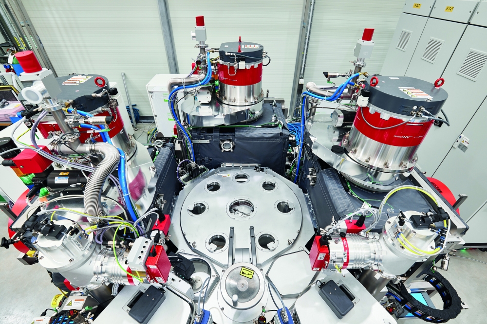
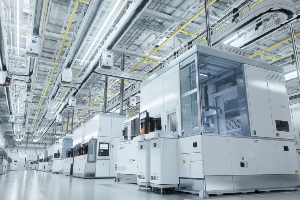
In the microelectronics industry, piping materials play an important role to ensure mission-critical fluid handling. Water in particular is an essential natural resource for semiconductor manufacturing facilities which use millions of gallons every day.
Extensive piping systems are therefore required for the transport of high-purity-, specified- water and wastewater as well as a variety of chemicals. Here, thermoplastics have established themselves as a popular option.
This popularity is due to several factors. Materials of construction such as PVC-(C), PP-H, PE, PVDF, or ECTFE feature a high chemical and corrosion-resistance, making them a long-lasting and cost-effective option. At the same time, thermoplastics provide a number of benefits that streamline projects and simplify the installation process. Jointing technologies such as contact-free infrared fusion with a completely machine-controlled process enable efficient and high-quality pre-fabrication, while the low weight of thermoplastics makes handling and logistics easier.
Moreover, thermoplastic piping systems directly support today’s most pressing industry challenges: a shortage of skilled labor, fast-paced facility ramp-ups, and the need to keep existing fabs operating reliably for longer periods. With faster installations, safer handling, and reduced need for rework, thermoplastics can enable semiconductor manufacturers to meet demand with greater agility and confidence.

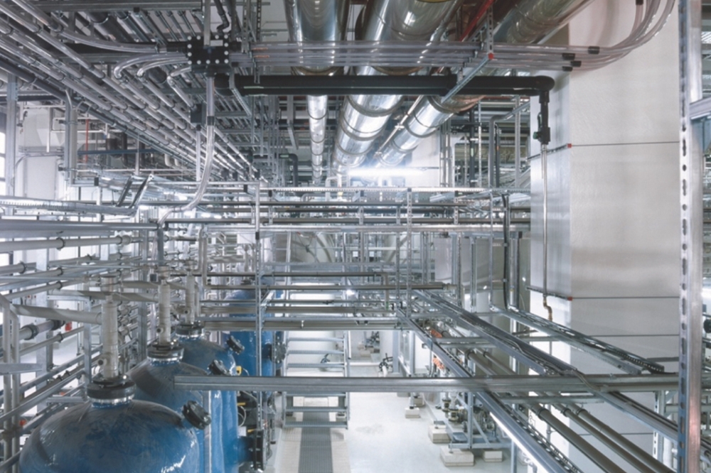
PSA is particularly important for long piping systems as they experience
unique stresses. Thanks to a thorough analysis, a Malaysian
semiconductor plant was able to achieve a max. utilization of 62% and a
safety factor of C > 1.6 over a length of nearly 20 kilometers.
Source: GF.
Understanding thermoplastics
Traditionally, guidelines for the design of piping systems are mostly based on steel as a piping material. However, the standards and material properties of steel cannot be simply applied to thermoplastics. One of the most striking differences is thermal expansion: A material such as PVDF, for example, has a thermal expansion that is ten times greater than steel (≈0.13 mm/(m*K) compared to ≈0.012 mm/(m*K). In practice, a wide range of factors need to be considered to ensure accurate results, including temperature differences between the installation and operation, the type of media flowing through the pipe, ambient conditions, and the length of the pipe.
Looking at the microelectronics sector, many modern production plants are complex and require extensive piping systems with transitions between buildings. As some sections might run through temperature-controlled interior spaces while others are subjected to the elements, these systems can experience significant temperature fluctuations. This is a crucial consideration during planning as thermal expansion can lead to pipe deformation, peak-stress areas, long-term creep failures or support damage if it is not managed correctly.
Another key consideration is the material behavior of thermoplastics, meaning the short- and long-term reaction to stress experienced by these materials. Similar to steel piping systems, short-term stress factors include pressure changes, water hammer effects, seismic activity, etc. At the same time, thermoplastics have unique long-term properties. For example, these materials exhibit creep behavior at higher temperatures or under long-term loading, reducing their elastic modulus over time. If planners are not aware of the specific material properties of thermoplastics or disregard some best practices, this might lead to catastrophic failure. In order to ensure the desired operational life span of ≥25 years for industrial piping systems, controlling the long-term creep behavior by a designed support concept is key.

PSA following a pipe rupture during a pressure test at a US semiconductor plant. The analysis showed peak stress due to large reaction forces and displacement, leading to a revision of the pipe support concept. Source: GF.
Why conduct a pipe stress analysis?
The goal of Pipe Stress Analysis (PSA) is simple: To predict and mitigate mechanical stress in piping systems, ensuring their structural integrity over time. The analysis process takes all relevant parameters into account, from thermal expansion to welding factors, modulus of elasticity, creep behavior, etc. This is especially important for an industry like microelectronics manufacturing which not only challenges planners with aggressive chemicals and high quality standards but is also experiencing rapid growth while facing talent shortages at the same time.
To meet demand, existing plants are being operated for longer durations and new plants are being built faster than ever. Pipe Stress Analysis enables optimum design for secondary support steel and supports planners in avoiding technical issues/claims as well as unplanned and costly downtimes.
Equally important, pipe stress analysis helps teams avoid inefficiencies during fast-paced facility builds. By identifying potential problem areas early, project leaders can proactively address stress factors to keep timelines on track — even when engineering resources are stretched thin. This makes pipe stress analysis not just a safety measure, but a powerful enabler for productivity and uptime.
PSA – Some best practices
1. Accurate Stress Calculations:
To ensure a reliable, long-lasting, and safe operation, it is not only important to take all relevant parameters into account. Planners must also calculate short-term stress and long-term deformation as thermoplastics react differently to temperature and stress over time.
2. Understanding your tools:
Many popular software options such as Caesar II are not optimized for thermoplastics. Alternatives like ROHR2 have been designed to correctly map both short- and long-term properties of thermoplastic piping systems.
However, software is only a tool, and the relevant parameters need to be defined by the structural engineer.
3. Load Case Mapping:
Over their lifetime, piping systems may experience a wide range of load cases that go beyond their intended operational parameters and can put significant stress on components, such as water hammer or seismic activity.
4. Engineered Pipe Support Concepts: An engineered and designed pipe support concept is essential, as it takes the specific properties of the pipe material into account. While traditional clamps for metal systems are rigid, thermoplastic require specialized supports that allow the pipes to move naturally without damaging them. There are many different support types to choose from (e.g. guide and slide bearing options, spring hangers, expansion joints, etc.).
5. Adherence to standards/guidelines: A static evidence according to DVS 2210-1 et al, using correct parameters for thermoplastic piping systems, meets or exceeds the ASME B31.3 guidelines for process piping and ASME NM.3.1 standard for nonmetallic materials. Some countries require a static proof by law (e.g. AwSV § 43 for double containment piping systems in Germany)
6. Analyzing existing systems:
Ensuring a reliable service life of 25 years or more is not just a matter of getting the initial planning right. Existing piping systems should be tested non-destructively in regular intervals. Should any stress peaks or deformation occur, it is advisable to conduct a condition assessment in collaboration with the manufacturer.

As prefabrication is a popular choice in the
microelectronics sector, unique stresses like acceleration forces during
transport also need to be taken into account. Shown here is a
prefabricated module with a size of ~ 6x6x21 meters
(~ 20x20x70 Feet). Source: GF.
Taking prefabrication into account
Like other modern industries, projects in the microelectronics sector often face challenges such as a shortage of skilled labor, time constraints, cost overruns, quality concerns, or physical space limitations. Off-site prefabrication has therefore become a popular choice as flow solutions are assembled in a controlled environment by specialists, which significantly streamlines projects.
Additionally, thermoplastic materials are ideally suited due to their low weight and versatile jointing options. However, prefabrication is yet another factor that should be accounted for in the planning phase.
This particularly applies to the transportation of components to the job site. Temperature variations and the lack of operating pressure can put significant stress on thermoplastic pipes. At the same time, transportation can cause acceleration values of ≈ 0,5g to 0,8g which may lead to impact damage. Including these load cases in the initial stress analysis ensures the structural integrity of the pipe spools, while additional, designed supports can mitigate issues like displacement during transport.
Solving failures with pipe stress analysis
Pipe stress analysis is also a valuable tool when it comes to analyzing and resolving claims. This is best illustrated by an example from the field which occurred at a semiconductor manufacturing facility in the US: During a pressure test after a pipe installation at elevated temperatures of around 60°C, the system experienced a pipe rupture with a violent break as a result of slipping off the slide bearings.
After conducting a pipe stress analysis, it was confirmed that this area of the piping system was experiencing peak stress due to large reaction forces and displacement. The issue could be solved by revising the pipe support concept and retrofitting guide bearings that prevent lateral as well as vertical movement and are better suited for maintaining alignment in this scenario.
Best practices from the field
Swiss flow solutions provider GF was chosen as a supplier for a state-of-the-art microelectronics fabrication plant in Malaysia. The plant required an extensive piping solution for ultrapure water and wastewater with a total length of nearly 20 kilometers, necessitating a thorough PSA.
Rather than merely supplying products, GF was able to support the customer as a collaborative engineering partner, and contributed technical insights as well as problem-solving expertise across the project lifecycle.
To meet the demands of the application, the pipe stress analysis focused heavily on the unique stresses associated with the considerable length. Among the most important parameters were peak stress and forces, peak displacement, as well as water hammer. These calculations resulted in the installation of ≈18 kilometers of polypropylene ranging from d20 to d500, and ≈1 kilometer of PVDF ranging from d20 to d160. In addition, the support concept and structural interface was optimized based on the results of the PSA. By conducting a thorough analysis, selecting suitable materials in the correct dimensions, and developing a compatible support concept, it was possible to achieve a safety factor of C > 1.6.
As part of the defined pipe support concept, selecting appropriate support types was key. Based on the results of the pipe stress analysis, the decision was made to change slide supports in certain sections of the piping system to guide supports. During the project, the customer selected Stress Less® supports by GF, a product family designed for PP, PE, PVC, CPVC, ABS, and PVDF pressure, waste, and double-contained piping systems. Stress Less® covers multiple installation configurations incl. guides, vertical supports, hangers, and valve mounting inserts.
The Stress Less® guide supports that were selected for the Malaysian Semiconductor FAB feature a metal bracket with a plastic insert. The clamp provides strength, e.g. during seismic events, while the plastic insert protects the surface of the pipe.
A consistent engineered gap between the insert and pipe diameter allows free movement and controlled friction in the axial direction during thermal expansion. Stress Less® also includes valve supports with threaded mounting inserts that allow valves from GF to move up to +/- 3 inches (≈ 7,6 cm).
Conclusion
Pipe stress analysis is an integral part of planning any industrial piping system, and especially for state-of-the-art semiconductor manufacturing. In order to ensure a long-lasting, reliable, and safe operation, understanding the characteristics of the piping material is key.
Due to a large variety of different thermoplastic resins being used, it is the responsibility of the calculation engineer to use correct material parameters. As a consequence, the specific life-time verification of a thermoplastic piping system can only be realized by using correct calculation parameters approved by the system manufacturer.
Despite the differences compared to steel, thermoplastics provide a wide range of significant benefits for applications in the microelectronics industry. Adhering to PSA best practices designed for thermoplastic piping systems not only streamlines the planning phase, but also enables the optimization and expansion of existing systems. This ensures maximum performance and peace of mind for operators.