
Invisible materials: on-site bulk gas supply to semiconductor and display fabs
Cost-effectively ensuring a supply of bulk gases at sufficient purity is essential for every semiconductor and display panel fabricator. The experts at Linde Electronics discuss the reasons for this.
By David Pilgrim, VP Business Development, Electronics, Asia Pacific and Dr. Paul Stockman, Head of Marketing, Linde Electronics
What material is produced on demand, delivered continuously with 99.9999999% purity, and is equivalent in weight to 500 elephants per day, but is never seen? The gaseous nitrogen delivered to a 3D NAND fab.
Nitrogen is just one of the bulk gases which are essential at every process step and tool for semiconductor and display manufacturing. As a category, they are often the largest bucket of material spend after silicon wafers. Not only are they physically invisible, they are ubiquitously available throughout the fab, and easily overlooked. Adjacent to every major fab is a bulk gas supply facility, which is constructed in parallel with the main fab shell, and which needs to be qualified and ramped before the first tool moves into the building.
In this article, we begin by discussing the commonly supplied bulk gases at semiconductor and display fabs, their applications, and their sources and supply options. Following, we describe the infrastructure required for the supply, and give an overview of the project steps to build this key facility.

Table 1. Bulk gas applications, sources, and supply.
Bulk gases, applications, and supply optionsIn addition to water, bulk gases are the simplest molecules used in electronics manufacturing. And like water, they are piped throughout the fab to be available in almost utility-like supply. First, we look at six gases that are commonly produced for many different industrial processes, but which receive special production or purification for electronics-grade use. In addition, we include five ESGs (electronic special gases), which are produced by chemical synthesis and used in such large volumes that bulk supply and delivery methods apply.
Bulk gases and applications
Nitrogen (N2): Ultra-high purity nitrogen is required during fab construction as the first infrastructure pipes and tubes are being welded together to exclude oxygen, moisture, and particles from the future supply to production tools. Eventually, nitrogen is fed to every tool as part of the overall process flow, which keeps the semiconductor wafer free of all contaminants, from incoming inspection to final qualification.
Nitrogen is used to purge any ingressed air and residual process chemicals, and to keep the wafer and all production wetted surfaces and spaces free from oxygen, moisture, and particles. Nitrogen is also used to purge vacuum pumps, which need a constant gas flow even when the tools are idle, and abatement equipment, which could be subject to pyrophoric conditions if air were present. Along with oxygen and argon, nitrogen is obtained by separating air into these three primary components.
Oxygen (O2): Ultra-high purity oxygen is used as a direct oxidizing agent to grow silicon oxide layers, and in more complex deposition and etch steps as a co-reactant. In addition, industrial grade oxygen is supplied to the abatement equipment as an oxidizer to turn reactive waste gases into less hazardous and more easily removed compounds.
Argon (Ar): Argon is used primarily to support plasmas for deposition and etch reactions. It is also used in deep UV (ultra-violet) lithography lasers and as a specialized cryogenic cleaning agent.
Hydrogen (H2): Hydrogen is used for epitaxial deposition of silicon and silicon germanium and for annealing of oxidized surfaces. More recently, it is also used in high volume as a cleaning agent to remove tin from the light sources of extreme UV lithography tools.
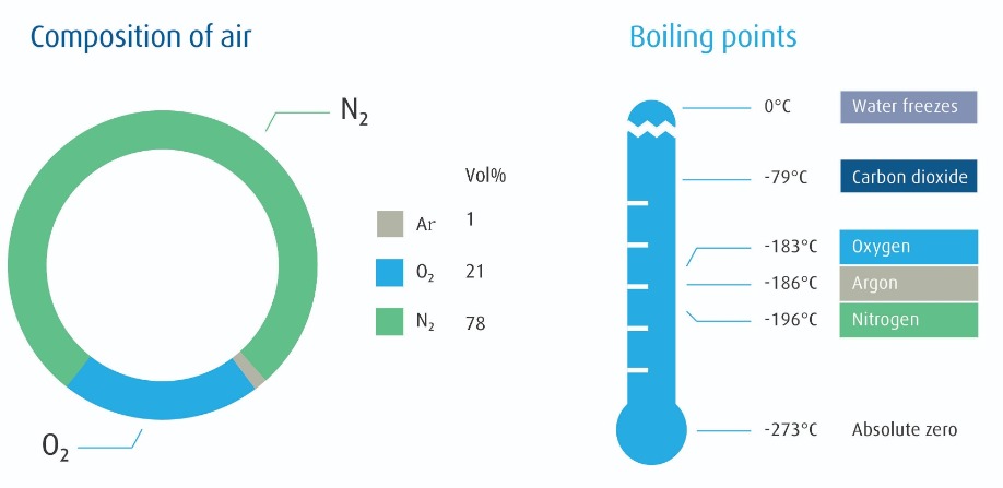
Figure 1. Bulk gas supply components
Hydrogen is obtained either by the catalyzed reaction of hydrocarbons with water, which is referred to as reforming, or by the electrolysis of water. Traditionally supplied by truck to the fab as a bulk gas or liquid, leading-edge fabs with high hydrogen demands can benefit from on-site production.Helium (He): Helium is the second lightest element and coldest liquid and is used in electronics manufacturing at hundreds of points in the fab for back-side wafer and load lock cooling, plasma processing, and leak detection. While helium is the second most abundant element in the universe, it is relatively spare on earth: produced as a by-product of nuclear decay of heavy elements in the Earth’s crust, it accumulates in the same geological deposits as natural gas.
However, only a few such natural gas deposits have sufficient amounts of helium to make it economically viable for separation, purification, and supply. It is liquefied to -269OC and shipped around the globe in vacuum-jacketed containers, often taking several months to deliver from the point of production to the point of use.
Carbon dioxide (CO2): Two applications predominate for CO2 at leading-edge fabs. Immersion lithography tools employ a thin layer of water between the final optical lens and the wafer surface to create a sharper focus of the light and enable smaller features. CO2 is added to water to displace dissolved nitrogen, which can create microscopic bubbles that distort the intended patterning.
Small amounts of CO2 are also added to the ultrapure DI (deionized) water in some fab applications to increase the conductivity of the water and thereby safely dissipate any electrical charges that can attract small particles. CO2 is obtained as the by-product from industrial production of ammonia, fertilizers, and hydrocarbons, and can also be captured from the production of hydrogen by steam reforming. Special care is required to ensure the purity and consistency of CO2 supplies to the semiconductor industry.
Bulk ESGs – Ammonia (NH3), Hydrogen chloride (HCl), Nitrogen trifluoride (NF3), Nitrous oxide (N2O), and Silane (SiH4): ESGs were originally supplied to fabs in individual gas cylinders. Now, the size and intensity of leading-edge fabs, in terms of wafers under production and number of process steps, has grown the demand for these five important gas-phase chemicals to such large volumes that they need to be supplied to fabs in ISO containers to sustain supply chain logistics and economies of scale.
Other than SiH4, which is shipped as a compressed gas, these materials are delivered to the fab site as pressurized liquids, and then vaporized before distribution to the points of use. They are primarily obtained from chemical synthesis of industrial chemical feedstocks and further purified. NF3 is the exception: it is made and used almost exclusively as a material for electronics manufacturing.
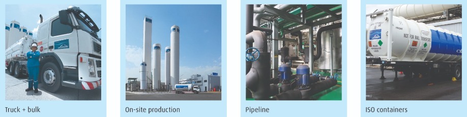
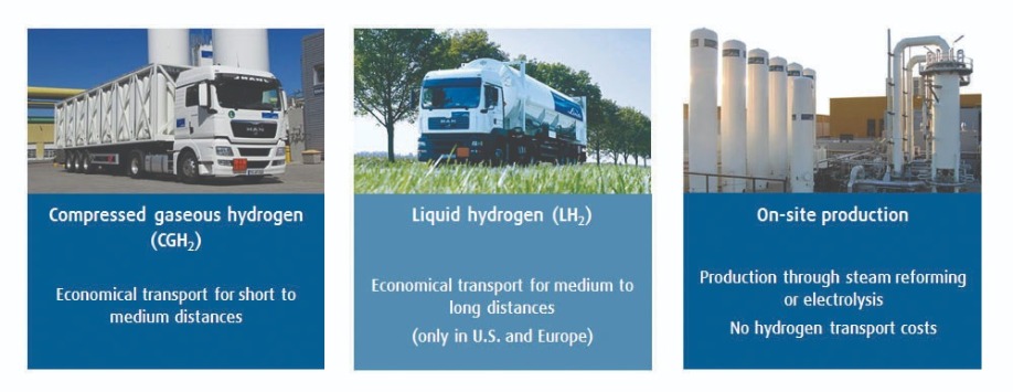
Figure 2. Volume and distance determine the most economical supply modes
Supply optionsScale, purity, reliability, cost. All of these are factors which have driven the supply of bulk gases to the level of requirement today. Below, we sketch the choices available to deliver bulk gas materials to optimize these four variables.
Air separation: This is the primary set of processes used to obtain nitrogen, oxygen, and argon from the air. Moisture, carbon dioxide, and other impurities are firstly removed from the air by chemical absorbers. The air is then cooled by successively compressing and expanding it until it turns into a liquid, which is then distilled into these three components. Electronics-grade air separation units can produce these gases to >99.999999% purity. Because argon makes up only 1% of air by volume, it is often not economically sensible to produce with smaller plants.
Liquid vs gas: It takes about three times as much electricity to produce these products in final form as liquids compared to the gas phase. For gases made on-site, it is therefore most economical to produce most of them as gases which are supplied on-demand immediately to the fab, with a small portion liquefied for storage and redundant supply.
Truck delivery + bulk tank: The economies are different for products delivered by truck. Because gases are much less dense than liquids, it would take five trucks to deliver the same amount of gas-phase product as one truck of liquid-phase product. The cost of transportation is therefore the overall cost driver; products are liquefied for transportation and then vaporized on-demand for use.
On-site production: Scale is the determiner for on-site production vs. truck delivery. For nitrogen, almost all 300 mm fabs and new display fabs operate at scales which require on-site production of nitrogen: to reduce cost, to ensure robust supply, and to produce to the highest and most consistent purity standards. Often, the demand for ultra-high purity oxygen requires an on-site plant to achieve the required purity specifications. And at leading-edge semiconductor plants, the use of epitaxial processes and the adoption of EUV lithography are twin drivers affecting consideration of on-site hydrogen production.
Pipeline: In certain locations, fabs are co-located into clusters or science parks. This allows for even greater economies of scale, as a pipeline can network the supply from larger gas plants to multiple customers.
Redundant supply: Regardless of the primary supply, electronics production requires extremely high guarantees of supply; therefore, redundant sources and supply schemes must be put in place. Most often, this means having one or more qualified remote sources, as well as liquid storage on-site equivalent to several days of production demand.
Integrated supply: As leading-edge fab demands go ever higher, more options become available for further cost reduction. A good example of what can now be achieved is the Linde SPECTRA® I integrated production on-site nitrogen, oxygen, and argon generator. Not all the nitrogen and oxygen used at the semiconductor fab needs to be the highest purity: some of this gas is going directly to vacuum pumps and abatement equipment downstream of wafer processing equipment. The SPECTRA I on-site gas generator allows a customized blend of production of both ultra-high purity and technical grade nitrogen and oxygen as well as ultra-high purity argon, thereby satisfying a large portion of the high-volume gas requirements from a single plant.
Purification and analysis: Because nitrogen, oxygen, argon, hydrogen, and helium are used in many different processes throughout the fab, including those most sensitive to contamination and chemical reaction, these materials are often further purified. Already produced with only part-per-billions impurities, on-site purifiers ensure these levels are reduced to consistent part-per-trillion levels.
ISO containers: ISO containers, short for the International Organization of Standardization intermodal containers, are the largest supply container options for bulk gases and ESGs. These are designed to fit standard distribution requirements on truck trailers, rail cars, and container ships. For liquid products with extremely low boiling points, these are vacuum jacketed to preserve cryogenic product temperatures and extend the shipping times. Once on-site, dedicated supply bays with distribution manifolds connect them with the fab.
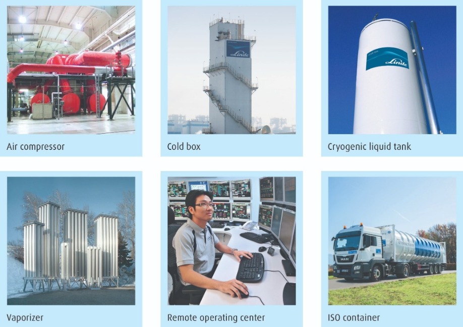
Figure 3. Bulk gas supply components
Project scope and executionScope
While there are many options available to semiconductor manufacturers with respect to bulk
gas installations, the primary driver is correctly sizing the demand. Adequate supply must be available for the fab, but without excess, so that cost is optimized. Once demand is calculated, two other major project requirements can be determined: land and utilities. Below, we examine these three factors in more detail.
Demand: Well-established manufacturers have existing fabs and processes from which they adapt and scale the gas demand and purity requirements for new fabs. New manufacturers, or those with new processes, need to make estimates based upon OEM recommendations and engineering models. In addition to average demand, peak demand – associated with recovery from an unplanned shutdown – must be calculated. Lastly, redundancy and back-up storage requirements are added. The aggregate demand and purity determine cost, and drive the optimized equipment solution.
Land: Once the equipment solution is determined, the footprint of land can be calculated. The manufacturer will need to include this in their overall land requirement. The gas yard can be contiguous to the fab site, or can be located on a separate parcel several kilometers distant. However, higher delivery pressures and larger pipeline diameters are needed the greater the separation of generation and use. Equipment plus land are the major capital expenses of the project.
Utilities: The equipment solution will also determine the utility requirements, which are primarily electrical power, water, and potentially natural gas for hydrogen generation. These, too, must be determined and included in the overall utility supply to the fab site.
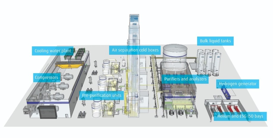
Figure 4. Gas yard layout
Major componentsNext, we will introduce the components of the gas yard that determine the overall footprint.
Compressors: These are the mechanical workhorses of liquefying and separating air. By compressing air, which is later expanded, the air is reduced in temperature until it liquefies.
Cooling water: A cooling water plant is needed to keep the temperature of the compressors within operating requirements.
Pre-purification units: Air contains moisture and carbon dioxide, along with more trace impurities. Adsorber-based purifiers remove these ahead of the cooling stage to avoid freezing and blocking of the air flow.
Cold box: This insulated, high-profile structure is the tallest and most prominent component on site, and is where the key liquefaction and distillation equipment is housed.
Bulk tanks: Bulk gas tanks hold both liquefied gas produced on-site as well as intermediate storage for other gases brought to the site as liquids.
Vaporizers: While these materials are most economical to ship and store as liquids, they are distributed and used in the fab as gases. Vaporizers are heat exchangers, which use heat from the ambient air or external sources to boil liquefied products to gases.
Purifiers: As discussed earlier, further purification is applied to these gases. These purifiers are catalysts and activated metals which remove residual impurities. They can be sited in the gas yard and/or the customer fab.
Analyzers: Throughout the production process flow, bulk gases are measured to ensure they are at expected purities and the process is in control. Analyzers that deliver such high sensitives must be housed in climate-controlled rooms.
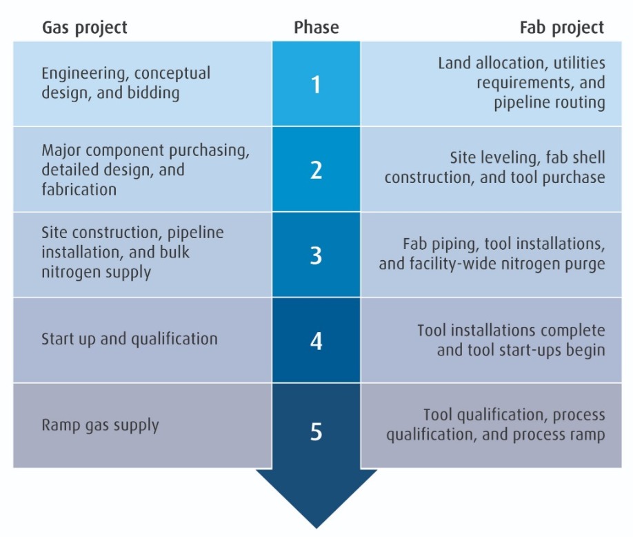
Figure 5.Bulk gas supply project timeline
Execution: General timelineFinally, we give a general timeline for bulk gas projects to show the correlation with the overall fab project, and to illustrate the importance of advanced planning to ensure the necessary supply of gas materials the fab when required. This timeline begins after the manufacturer has determined its process flows and tool requirements. Planning and construction timelines vary depending on the size, scope, location, and scale of the project.
Phase 1: The manufacturer kicks off the bidding process by providing gas demand and purity requirements to gas suppliers. These in turn make their engineering and conceptual designs to determine their own equipment requirements. In feedback to the manufacturer, these help in the specification of the total land and utility needs.
Phase 2: After the bid is awarded, the gas supplier begins purchasing major components, and moves to detailed design and fabrication. The manufacturer is preparing the site, including the gas yard, constructing their fab facility, and placing tool orders.
Phase 3: The gas supplier begins its construction project. The first two installations are the bulk nitrogen supply tank and the pipelines connecting the gas supply to the fab. At the end of this phase, the two projects are linked: bulk (trucked in) nitrogen begins to supply the fab shell to purge the piping of the facility and the first tools are installed.
Phase 4: At the completion of the gas yard fabrication, the on-site generators are started up and qualified. The bulk gas and back-up supply chains begin. In the fab, tool installations are completed and tool start-ups begin.
Phase 5: The fab continues its project with tool qualification, then process qualification, and finally begins its process ramp. This increasing activity raises the gas demand, and the gas supply ramps in response.
Summary
Bulk gases are a significant portion of supply spend for semiconductor and display fabs. Effective supply often requires on-site production, storage, and distribution. These facilities are built concurrently with the fab, and the first qualified gas deliveries are made as soon as the fab shell is complete.
Because of the magnitude of the project in terms of land allocation, utilities infrastructure, and capital spend, bulk gas suppliers work with electronics manufacturers from the inception of new projects to properly size, equip, and execute bulk gas facilities to supply and ramp the project. From the first patents and equipment for the liquefication and separation of air over 120 years ago to the largest and most efficient plants today, Linde plc is a leader in providing customers the products and solutions they need. Linde Engineering designs, fabricates, and executes facilities for the production of nitrogen, oxygen, argon, hydrogen, helium, and carbon dioxide, with thousands of plants in operation around the world. Linde owns and operates many of these plants for customers, including leading semiconductor and display manufacturers. Notably, it has pioneered the science park model of supplying many customers and fabs with collective production in places such as Taiwan, South Korea, Malaysia, and mainland China. And it supplies the world with helium from a diverse portfolio of sources and supply chain investments.


